The EFW “Skookum Choocher” 40-6m Portable Antenna w/ 9:1 Un-un

Over the past few months I have taken a fancy to QRP portable operation. It has been a big thrill for me to go to a local park or forest and throw up and antenna to see what stations I can work with 5 watts.
I decided to invest in a small portable HF radio, the Elecraft KX-3. I chose the KX3 mainly because of its ultra small size and awesome receiver performance. But having a good QRP radio is only part of the equation. Having a good antenna is also just as important as the radio as you need to get those 5 watts to work for you.
I checked out several designs online. From the humble dipole to portable vertical style antennas. Although I don’t plan on just using one particular antenna, I wanted something that I could deploy quickly and as easily as possible. After searching about, I found plans for a End-Fed random wire antenna that was fed by a 9:1 un-un that would work mult-band 40-6m. Seeing from the plans that this antenna looked easy enough to build I started construction on my own antenna. *Note – this antenna will require a tuner for multi-band use!
I had just a few requirements really…I wanted to build this antenna with things that I found lying about so that I spent really nothing to build it. However it really wouldn’t cost much in parts anyway to build. I found an excellent PDF article from EARC Amateur Radio Club. Here is a link to this PDF file: http://www.earchi.org/92011endfedfiles/Endfed6_40.pdf
Here is a parts list that I used to build my 9:1 un-un box:
- The box. Plastic would probably be better for water resistance, but a metal box will be fine if you keep it dry.
- A powdered iron toroid core T-130-2 (I used a slightly larger toroid because that is what I had lying about).
- 3 20″ pieces of 22-18 AWG wire (solid conductor works best -red, green and black colors). However I used different wire that was white, red and black because that was what I had laying around.
- 2 binding posts (this can be also bolts with wing-nuts and lock washers to fasten to the un-un box). I had binding posts so I used them (and they work nice to quickly remove wires!)
- A Chassis mount SO-239 connector.
- Various nuts, bolts and fasteners (depending on your construction).
- A soldering iron, solder, and a bit of RA flux
- A hot-glue gun (used to secure the toroid in the box)
- Basic hand tools (screwdrivers and pliers)
- 30′ of 18 AWG stranded wire
- 1 qty large diameter ring wire terminal lug (this is used to put a ring on the end of the wire antenna so that you can hang it or raise and lower the wire antenna.
After looking through my junk box (it would seem that every ham radio operator has a box of junk lying about) I found an old TV signal amplifier box. The box is an all aluminum box, so I thought this would be good to ground connections and keep everything contained. I gutted all the electronics (it was a good thing anyway since this device had a live chassis to mains voltage! – If you have one of these laying about don’t use them. They are not safe). I drilled some holes in the metal box to accommodate a SO-239 and the binding posts that I could connect my antenna and counterpoise to.
 The gutted Wineguard TV antenna amplifier box I used as the chassis.
(Note the SO-239 connector – I drilled out the hole and used rivets to attach SO-239 to chassis)
Next I needed to wind the toroid. This was actually pretty easy and I learned a few things to help make it an easier process. I found that if I used zip ties that I could hold the wire in place easier. This may not be the best solution for you, but for me it did help. Every time that you put a wire through the center of the toroid core means that the wire has been wrapped once. So that is an easy way for you to keep track of how many turns you are making. Since this is a 9:1 un-un, you will make 9 turns around the core. (Easy right?) You start by taking all 3 wires (red, green, and black) and wrapping them 9 times around the core.
 The 3 wires wrapped 9 times around the toroid core. Try to keep the coils around the torid core evenly spaced. Make sure wires do not overlap.
Once that is done you will connect the left hand black wire and the right hand red wire. You will need to trim the wire a bit since they still may be long:
 The wound toroid with the red and black wires
For the last bit with the winding of the toroid you will need to connect the other end of the red wire with one end of the green wire:
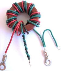 The black and the green wire. Leave them long as you will need to connect these. Also you can add ring terminal lugs if you wish to the red and green wires to more easily connect them to the biding posts, or bolts with wingnuts that you will use for the counterpoise and wire antenna.
The twisted green and black wire will be soldered to the SO-239 connector’s center conductor. The end of the green wire with no connector will be soldered to the shield of the SO-239 connector and the green wire with the ring terminal will be attached to the binding post or bolt that you use to connect the counterpoise wire to. The red wire with the ring lug is used to connect to your antenna binding post or bolt.
Here is a picture of the assembled antenna showing the connections in an enclosure:

That photo really shows the connections to very well. You can see that the bolt with the wingnut that is on the top is connected to the red wire. This is the antenna connection and where you will connect your 30 feet of wire that you will use as the antenna.
The bottom bolt with wingnut is the counterpoise connection. You can add 15-20 feet of wire to get your SWR just right, however you may not need a counterpoise most of the time for this type of antenna design as it will use the shield of your coax cable as the counterpoise.
The SO-239 coax connector is used to connect your radio to the antenna. If you use this type of antenna a minimum of 20 ft of coax is recommended as the shield is used as a counterpoise. If you want to use a shorter piece of coax to connect to your radio, then attach a 20 ft piece of wire to the counterpoise connection and lay it on the ground.
Here are pictures of my particular build:
 This is my toroid that I wound. Note the white, black and red wire (I had this wire lying around so I used it).
 My box with the binding posts, 9:1 toroid transformer and SO-239. (Note the terminal strip a the bottom right. This was already in the box so I decided to use it as a convenient place to make my connections!)
The end product with the case on and my custom labels!
After the build I decided to take it out and give it a try. I connected my 30 foot piece of wire to the antenna binding post and then sent the other end skyward into a tree getting it up around 25 feet or so (I could have probably got it higher, but this was good enough for testing). I connected my 20 ft of coax to my Elecraft KX-3 and then powered it on.
Using the built-in tuner on the KX3 I was able to tune up on the 40m band with a 1.2:1 SWR on 7.185 MHz.
I tried the antenna on several other bands, taking note on how difficult it was to tune using the KX3’s ATU. I also tried it on 80m and was able to tune it with a decent SWR (2.2:1) Although this antenna just wont work well on 75/80m (it is to short and the wire is not high enough).
Just in the front yard, I decided to setup my QRP portable station:

I used my KX3 transciever, the PX3 panadapter and a 6AH Bioenno branded LiFePO4 battery to power it all. I made several US contacts using 5-10 watts and the end fed antenna that day, including a QRP contact to Ireland on 20m! I found performance on 20 and 40m to be superb with only 30 feet of wire. Conditions were good as it was spring time 2017 and the bands were in good shape. I am always blown away by the fact that you can use 5 or 10 watts and talk so very far away. QRP has been a lot of fun and I cannot wait until the winter is over so I can get back outside. (At the time of writing this article it is January 2018 and is -15 degrees here at my QTH in NW Indiana).
My verdict is that this antenna is a quick, cheap, and easy to build and deploy antenna that should be considered for QRP portable ops. I still tend to use dipoles as they work very well, but there are times when you may not be able to have 3 supports for the center and two ends of a dipole antenna. This antenna solves a lot of problems for portable ops such as the support of the antenna, quick deployment and stealthy deployment if you don’t want to attract a lot of attention.
If your into portable ops I urge you to give this a try. Although you can buy antennas like these for $40 – $100 I urge you to build it yourself. The satisfaction from building something, putting it on the air and making contacts with it is a joy to behold!
73! de Nick N9SJA
