RF Oscilloscope sampler
 Here is a little project that I put together a few weeks ago while playing around at my club W9YB.
It is an RF Oscilloscope sampler designed to connect in-between your transceiver and antenna to display the signal out of your rig.
This project was inspired from episode #110 of Ham Nation titled “Bob Shows How to Connect Your Scope to Your Transmitter”. In this episode Bob Heil K9EID will show a basic schematic for the design that I have made digital here.
In my design I had to use two .01 mfd capacitors in parallel since I did not have the correct .02 value, but other than that I was able to scrounge up all of the parts that I needed as they were lying about at my club station at W9YB. This is just one of the many projects that several folks put together spontaneously at W9YB, usually on a Friday afternoon when we are there just hanging out.
I was really lucky to find this small box that was perfect for the SO-239 UHF style connectors and it housed everything I needed perfectly. I plan on building more of these with some other members in the future and using them to display the characteristics of RF on an oscilloscope.
Here are some more photos:
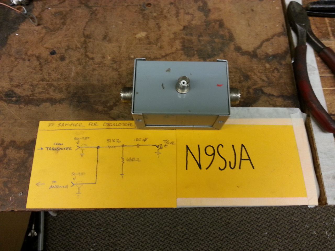 The finished product (sans the labels that I need :))
 The diagram of Bob Heil’s (K9EID) RF Sampler that I made
This was a very easy but fun project to build. I really had a blast using this and analyzing the RF signal of some of the HF radios at W9YB.
Feel free to download the schematic and build one for yourself. And if you would like, let us know how your build went in the comments below.
73! de Nick N9SJA

Great looking RF Tap!
What are the resistors and caps rated for? 1W?
Thanks and 73.
There are two ways of figuring the rating of the resistors. One way is to observe that the resistor circuit is about 50k ohms, and the antenna is supposed to be 50 ohms, so you might figure that about 1/1000 of the power goes through the resistors as opposed to going to the antenna. For 150 Watts (the output of the transmitter that I use most often) that means that it might take 150 mW. So, 1/4 watt resistors would be fine, and you could use 1/8 watt if you had a mind to.
The other way is to say that 150 Watts into 50 Ohms means that the signal averages 87 volts (P = V^2/R) and 87 volts across 51K ohms is 0.148 watts. Again, 1/4 watt or better should work just fine in that case.
As far as the capacitor(s) is concerned, those are probably just DC blocking capacitors, and I can’t imagine that 10 nF caps would be all that much different for that purpose from 20 nF. You’re just looking for a small reactance compared to the 680 ohms to ground. The thing is, most transmitters don’t put DC on the output. I think that aspect of this design is likely a holdover from the days of tube radios, where you had to worry about the DC blocking capacitor on the final amplifiers failing short and putting thousands of volts of DC onto the antenna. Anyway, I’d probably use about 5KV because I actually DO have tubes in my finals, and I’d worry about 1000V or so on the feedline. Of course, I could be wrong.
What should be the wattage ratings for the resistors,
And what type of capacitor, polarized(?), and the voltage rating for the capacior?
Just wondered…
Especially if i just leave it in circuit for continous use
..just for yucks and giggles…